Finite ELement (FE / CAE) Elements tools: the Elements Tab
Time to read: ~9 min
The Finite Element (FE) Tab is by default disabled/hidden and is activated either by loading a FE type mesh or by loading a CAD style polygon file and then using the
'To-FE' option on the Import tab.
In the previous InStep application, the FE elements options and the regular (Body-Feature-Polygon data) was lumped onto the same level of interaction and some options
could be chosen for either formats.
With the InStep Studio application, the two domains are more separated as the two formats fulfill very different roles and some users may never use the application for any
form of interaction with the Computer Aided Engineering type meshes that these tools are aimed at. For this reason, the Elements tab is hidden by default until either the
corresponding data is loaded or regular data is explicitly converted.
The standard view for the Elements tools is shown below:
 Elements Tab
Depending on the data loaded, different options are available (those buttons that are not greyed-out). If the Application settings are such that the import of data is
to consider a maximum number of elements for conversion to display data, then it is possible that either no data is shown after loading a file or a simple box representation
is used. This option is useful for cases where very large data sets (tens or hundreds of millions of elements) are loaded which could overwhelm or unnecessarily slow down the
process (depending on the process, displaying data may not be necessary). If no display data is shown it can be Extracted, see below.
 Extract
This option extracts a surface representation of the Elements data loaded. The default (which can be modified from the Application Settings) is to extract surface information
from Shell elements if they are present (and imported, also an option) and otherwise extract from Solid elements. If the number of elements is above a threshold (1,000,000 by
default) then the extraction process is skipped in favor of better performance. In this case, this option to extract the surface representation is available.
The setting to use 3D or 2D elements (more correctly Solid and Shell elements, respectively) allows selection of which type of element to prefer for obtaining the surface representation.
In the case of a value of 'Auto', the application chooses which to use (Shells if there are, Solids otherwise). 'None' will skip loading and use a box representation instead.
 Add 2D
Some applications require that the exterior surfaces are defined by means of Shell Elements. If the original data only contains Solid elements, then their surfaces can be used to
add Shell elements automatically and will consist of either Triangle or Quadrilateral Shells, depending on what element represents the surface on the exterior (Tetrahedral elements
will always generate Triangles as do the sides or Pyramids and Top/Bottom of Prisms. In other cases, Quadrilateral elements are generated).
 Remove 2D
Similarly to the Add2D option, this removes any Shell elements contained in the data from the Elements. The graphical data (and thus the Polygon data available for export) is not
directly affected.
 Mid-Plane
The Mid-Plane option is another way to generate Shell Elements from Solid Elements. It works by intersecting all elements with a Plane (defined by one of the Coordinate Planes or
determined by which plane defines the most dominant data sets) and then generating either Triangle or Quadrilateral elements from those points. This tool is intended to allow
simple Solid Element bodies to be quickly converted to Shell Element Bodies for use in Structural CAE models.
 Tri > Quad
The Tris to Quads converter is a way of converting Triangular Shell Elements into Quadrilateral Shell Elements. Some applications benefit from having Quad type elements rather than
Tris. The approach used here is to first match neighboring triangles and then to attempt (if the check box for pure quad is set) to iteratively merge any remaining items.
The first step, to generate a quad-dominant mesh succeeds in all cases where the original mesh is correctly defined. Converting to a pure quad mesh succeeds if
the number of triangles is an even number and no vertices become non-manifold in the process.
 Quad > Tri
The Quads to Tris conversion is aimed at cases where a Quadrilateral based mesh may be provided but the target application can only process Triangle data. Each Quad is split
into two Tri elements along the diagonal.
 Refine 2D
The refinement tool is specific to the FE Mesh elements and performs a modification of the Node locations. In order to maintain the boundary of a shape, Nodes located on the
periphery are prevented from moving other than along the perimeter. Internal Nodes are re-positioned based on an averaging of the surrounding Nodes. In general, performing
multiple iterations of this can lead to better quality elements though care must be taken to prevent items from changing too much and becoming problematic for the target
solver.
 Remove Solids
This option deletes all Solid Elements from the data sets. The process does not re-number element IDs that remain and also does not remove Nodes associated with the elements
being deleted (see the Clean tool).
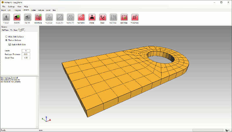
 Inflate
Elements: Inflate Main Page
The Inflate tool is aimed at two cases: Generating a thin, prismatic (boundary) layer on top of existing elements and to convert Shell Elements to Solid Elements.
For more information see the detail page for this tool.
 Clean
Clean
The Clean tool performs data Clean-up: during the process, all current elements are interrogated for Nodes that they use. Any Nodes that are unused are removed from the
data set. All Elements that are undefined/unused are removed and their Element ID values re-labeled to be continuous, starting at Element 1. The Elements' Node ID values
are re-assigned based on which Nodes have been removed. This process allows unused data to be removed, resulting in a more compact output, especially if different tool options
have been applied to the Element or Node data sets (if Shell or Solid Elements have been removed, their Nodes, though unused, would still be present in the output).
 Del Sides
If the original data contains Hyper-Elastic Elements (Elements that not only contain Nodes at their corners but also along each of the edges) then this option becomes available
and allows these nodes to be removed from the Elements' definition and makes the Element a regular type (so for example a TRIA6 is converted to a TRIA3, TETRA10 to TETRA4 and so on).
Most CFD applications will either require that mid side nodes are explicitly removed or remove them during import. For FEA type applications, Mid-Side nodes may be of interest for
cases that involve high deformations.
 Add Sides
As Hyperelastic elements are usually not the default element, it can be of interest to convert regular elements to allow special simulation modes where applicable. As it is not usual
to have this option after the mesh has been generated, having an external option to do so can be advantageous. This tool allows each regular element to be converted to its
hyperelastic equivalent by creating new Nodes that are located at the Element's half-way point along the edge. No change to the shape of the element is implied by doing so, but each
element is defined by more nodes and they remain coherently linked (neighboring elements share mid-side nodes).
 Transform
The Transform tool brings up a dialog box where the entire mesh can be transformed (either Translated, Rotated or Scaled). For the Translation of the mesh, each location is shifted
by a vector defined by a set of offset coordinate values. For a rotation of the Elements and Nodes, the rotation is defined by a center point, an axis and an angle. The Angle (given in degrees)
is the rotation around the axis using a right-hand rule.
Scaling of the data is by default accomplished by providing a uniform scale which multiplies each Nodes' coordinate value. Alternatively, individual scaling factors can be applied for each
coordinate which can squash/skew the data. For the case where a non-centered scaling factor is applied, each location is first translated, then scaled and then translated back.
Additional Settings
In the Menu:Settings > Application Settings under the 'Data' group are several settings that may need to be modified based on the circumstances:
- Correct Prisms
- Depending on the source of the data, it can occur that Prismatic elements (PENTA) have their top and bottom surface reversed. With this option
such cases are corrected where needed. By default, this option is enabled.
- ExtractElementSurfaces
- The options are 'None', 'From_2D', 'From_3D' and 'Auto'. This determines whether surface data is to be obtained using the Shell or Solid elements
(2D, 3D) or skipped (for large files that are not used for Body-Feature type CAD conversion. Auto uses a combined search that uses 2D where no
3D surfaces are defined though, depending on the configuration of the data, this can sometimes cause strange visual behavior. A 'From-3D' option is
generally recommended unless there is a mix with some surfaces being defined by Shells and others through Solid elements.
- LoadShellElements
- This option allows Shell elements to be skipped during import
- LoadVolumeElements
- This option allows Solid elements to be skipped during import
- LoadShellElements
- This option allows Shell elements to be skipped during import
- CorrectScale
- In some cases, the input data can be very small, to the point where working with the data becomes an issue. This value allows
a lower limit to be set below which (applicable to the diagonal of the bounding box) the data is scaled to be closer to a unit size.
- MaxAutoSurface
- If the ExtractElementSurfaces is set to 'Auto' then the application checks the total number of elements loaded. If there are more than this
value, the surfaces are not extracted (to help with memory/performance). A dialog box shows up instead providing a notification that
the number of elements exceeds this value.
Remarks
The main intent of the Elements options is to allow users to convert different file formats as well as perform some simple conversions and simplifications of the data.
The application is by no means comparable to high end dedicated CAE applications but attempts to be a vendor neutral in-between for cases where competitor applications may
not support a common set of file formats.
Additionally, as the InStep application aims to provide an option for importing Mesh data into a Boundary Representation environment, there should be no limit as to what the source
of mesh data is and having the option of importing a structurally deformed shape back into CAD to investigate its impact is frequently a useful option.