InStep Studio

INSTEP STUDIO 3D

Tutorial 4 - Editing and Repairing Data

A fairly frequent situation arises when the imported data contains issues such as overlaps, gaps, duplicate surfaces or similar. In this tutorial we will look at some of the tools available to perform repairs and edits to the imported data. The lessons learned here are applicable to a number of other situations too.

Other options for Reading/Learning

Alternatively, you may want to
Download as PDF
Watch the YouTube Video

The Example File for this tutorial is available here:
Example Monkey File (STL)

Please click on the items below as we progress through this tutorial

The InStep application is primarily concerned with the conversion of mesh to boundary representation (B-Rep) and therefore does not focus its capabilities on constructing or editing surface data directly. There are many tools available for free that do a very good job at editing, creating and manipulating surface/mesh based data. Our recommendation is the Blender application or Wings3D - though there are certainly many more that can fill this requirement.
Instead, the InStep application provides tools that help in some common tasks associated with correcting or modifying existing mesh data: the Edit and Repair tabs that will be presented here.

In this first section we will focus on the Edit tab.
Once the example has been imported (anyone familiar with Blender will recognize this as 'Suzanne'), the application will ask about splitting the body, as discussed in the previous tutorial. Performing the splitting operation on the body and then switching to the Edit tab will bring up the view shown below (note that the Messages Panel has been turned on as discussed in Tutorial 1) :

Edit Tab with Suzanne Loaded

Note that there are better ways to work with this body, but for now we will use this approach:

  1. Select (left mouse button click) any triangle in the left eye. It will show that it was selected by turning red
  2. From the options on the right, click the 'Flood' option, this will keep expanding the selection until an angle of 30 degrees or larger is encountered
  3. With the entire surface selected, click 'Delete' from the main tools, this will remove all surfaces of this eye.
  4. Click 'Accept' from the main tools, this will apply the pending changes.
  5. Repeat the process for the second eye, this time select a surface and then hit 'Grow' repeatedly until the entire eye is selected.
  6. It is possible that not all surfaces become selected. Press 'Esc' to clear the selection and use the 'Flood' option to select the entire eye. Perhaps try different values for the flood limit and different starting triangles. Using a value of 10 and selecting a surface in the center should limit the expansion to only the central region.
  7. With all faces of the second eye selected, click 'Delete' and then enable Edge views (Alt+E) and Vertex views (Alt+V). Observe that the edges and vertices are still present as the changes have not yet been applied.
  8. Click Accept.
  9. Use the middle mouse button (or click the mouse wheel) to select a point somewhere between the eyes. Then use the shortcut Ctrl+R to make the rotate-center visible (shows a pink dot).
  10. Rotate the shell body so that the view is from the inside, looking out through the eye sockets.
  11. Switch to the View tab and find the 'Lighting' tool button (if not all tools are visible, the size of the application may need to be increased/maximized). Click it and observe how the inside surfaces are made brighter. Turn this option off again.
  12. Switch back to the edit tab and check for any remaining surfaces from the original eyes, repeat the above steps to remove any remaining items.
  13. With the body rotated so that the viewer is located on the interior, select the 'Boundaries' option from the right-hand tools, the data should look like the figure below:
View from interior
View from interior outwards

If you cannot get the view to look the same, see the first tutorial on how to set the rotation center (middle-button click) and then to rotate it so that parts of the head are behind the viewer. Rotating/panning/zooming take some getting used to but get easier with use.
At this point, all surfaces that are not being used have been removed and the open boundaries marked.
It is possible to manually mark three vertices by using the 'Select' filters and then picking three points from the viewer followed by using the 'Create' button to generate individual facets, one at a time. This is a recommended approach for cases where single triangles/facets are to be repaired and replaced, but for items such as this, we will use the Repair tab with its options instead.

The Repair tab contains a number of tools that are intended to help resolve common issues. The tools available are accessed from the main tool bar and provide options for each type of repair tool:

Suzanne in Polygons tab
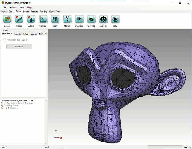
Suzanne Model loaded in the Repair tab

Each tool, accessed from the main tool bar under the Repair Tab, presents any applicable options. By default, when switching to the Repair tab, the 'Show Issues' option is selected, without performing the process of displaying the error data (see below). It is possible to switch to the relevant tool either by clicking on the main tool bar icon at the top or directly by accessing its options by selecting the tab item under the Repairs group in the left-hand section.

As this body is relatively small (contains 3,456 facets), the default settings can be kept. Clicking on the 'Issues' button in the tool bar, starts the process to determine the problematic items. After a few seconds, the display updates and shows that there are 52 Open Edges but no other problems where found.
An important item is to be mentioned here. The Intersections are tested for using a Axis Aligned Bounding Box (AABB) method which generally is fast and detects all but a few rare conditions of overlapping facets. It is possible to perform an explicit test for overlapping facets by enabling the 'Perform Full Test' option from the Repairs: Show Issues tab on the left. Keep in mind that this approach is far more involved as it performs an intersection test that test each triangle against each other triangle. We will run this here to show the difference for this very small file:

  1. Turn on the 'Perform Full Test' option from the Show Issues options
  2. Click 'Refresh All'
  3. After a few seconds (somewhere around 5-20s, depending on the computer), the process completes and updates the results

Though in this case, the time it takes to complete is not too painful, it can take several minutes for even moderately sized files so only use this option if absolutely necessary.

Even with a small file such as this, there is a small lag between running the test and getting results, even for the faster option. We will go ahead and turn off the automatic test for intersections:

  1. Change the Settings > Application Settings > Repair: AlwaysComputeIntersections => False
  2. Close the Application Settings (any changes made are automatically saved)
  3. Make sure that the 'Perform Full Test' is un-checked
  4. Click the 'Issues' button in the main tool bar to hide the issues being displayed
  5. Click the 'Issues' button again to show the data.

Note that in this case, the check box in the viewer for Intersections remains un-checked. This means that the Intersections are not being evaluated but can be requested by clicking the checkbox. It should also be noticeable that the other issues get displayed a lot quicker as the other tests are performed far quicker.
It is recommended that the Intersections are evaluated on a case-by-case basis but that the other items are checked for each file being used. If there are no other issues, then intersections are less likely so performing a basic evaluation as a first step is recommended.

Now that we have confirmed that there are two sections with Open Edges, we will close them using the Fix Holes tool, directly accessed from the main tool bar. Click the Fix Holes button and observe that the Repairs options switch to the Holes configuration.
Here we have a few options available:

  • Tessellate
  • Smoothed
  • Minimal
  • Bounded

For each of these options, the application will use a slightly different approach to close sections that have a (continuous) boundary of open edges. To see the differences between them, select one, then click on 'Preview'. After a second or two, the display updates and shows the result. You can pick a different option and click Preview again to see the differences. If the choice is acceptable, click 'Apply' to make the choice permanent. If you want to go back, you can click the red circle with a white 'X' in it to clear the preview and go back to the current state of data.

The approach presented is fine and works for a wide variety of cases. However, there are different ways to approach this that we will cover here. To get back to the same condition (Suzanne with both eyes removed), we do the following:

  1. Go to Menu: Settings > Application Settings
  2. Under Behavior, find 'ResetViewOnImport' and set to 'False'. Close the Settings.
  3. Go to the Menu: File and click the monkey_tutorial4.stl file from the Recent Files list (should be the first one)
  4. Select the Split option if the dialog appears, otherwise go to the Bodies Tab and pick 'Split' from the tool buttons then Apply
  5. Select the Bodies tab from the main tool bar
  6. Left-Click the main body/head from the viewer (turns red)
  7. Right-Mouse click anywhere in the viewer
  8. Click 'Delete All Others', this deletes the two eyes and brings us back to where we were...

Note that the option to Reset the view during import is generally useful but we disabled it for this case so that the orientation would remain when we re-import the file. In general, you will want to keep this turned On (=True) so that new data reset/re-centers the view.
Reset this Setting now ...
Now we still want to close the two eye sockets and we are going to be lazy and simply use the Automatic Repair option:

  1. Switch to the Repair Tab from the main tool bar
  2. Click the Auto Fix option from the tools
  3. Select the 'Basic' Method
  4. Click Preview
  5. The display updates and shows the same result as for the Hole Closure: Smooth option
  6. Click Apply to make the changes permanent

How is this different? Internally, the application uses a number of different options to perform automatic repairs and Hole closure is just one of them. By default, the automatic repair attempts different hole closure options (they don't always work, so attempting hole closure with one tool and then switching to another is a prudent approach). Before doing so, the application also removes other items that may be problematic. In general, it is recommended that for a body such as this where the 'issue' is quite clear the more direct, manual approach is chosen as there is more control by the user about what processes are being used and what the result looks like.
It should also be pointed out that the Automatic tools can take a significant amount of time to complete. The Basic and Extended methods are both quite fast and generally do not affect the underlying mesh by a large degree, but others, such as the Solidify tool can take a consideratble amount of time, even for simple bodies (as they do not rely on the original data beyond using it as a guide for what it should look like). There is an option from the Settings > Application Settings > Repair: UseParallelForRepairs which uses a multi-threading approach to some of these slower processes. It is recommended to turn these on when using a computer that has a powerful CPU; on laptops with only one or two cores, this may be best turned off (which is the default).

The other tools on the repair tab are without doubt of interest and more tools will be added over time if user feedback (issues reported through the Help > Submit Error Report) indicates that a specific tool would be of use.

For any of these tools, it is highly recommended that small files (such as the one used in this tutorial) are first used to get an idea of the level of complexity and time required to perform a given action. Equally, several of the tools have a setting or parameter that can be increased or decreased to get a rough or detailed result. First try with a lower setting as this will always process quicker. If a low value takes a very long time and consumes a large amount of memory, a high setting may result in the application appearing to 'hang' or even crash (if too much memory is being requested). Use common sense to work with these tools...

One item that does not get as much attention as it perhaps deserves is the tool for fixing Normals. A Normal is a vector that points away from the surface of a body towards open space. Mathematically, it is perpendicular to the surface and (should) have a unit length. What is important is that the surface has continuously outwards-pointing normals which is a property that is used in a number of tools and processes within the application. The Normals tool in the Repair tab is an automatic tool to correct the orientation of the vectors to consistently point outwards. One assumption that the tool relies on is that a multi-body file has been split into separate bodies. The second assumption is that it can find a good starting surface from which all others are derived. Usually, this all works well. Sometimes however, the starting surface is not as it expected it to be and incorrectly applies changes throughout the body. In those cases, it is up to the user to manually reverse the surfaces by selecting the body in the viewer and then using the Right-Mouse option to 'Flip Normals'. This reverses all faces of a given body. The dark grey appearance is an indicator that the 'inside' is being viewed.

<< Workflow with Expert Interface Modifying Body Data >>