InStep Studio

INSTEP STUDIO 3D

Tutorial 1 - Basic Overview

This should be your first tutorial, focused on the overall handling and use of the InStep Studio Application.
The information presented here will help you get acquainted with the layout and workflow presented during future Tutorials.

Other options for Reading/Learning

Alternatively, you may want to
Download as PDF
Watch the YouTube Video

Please click on the items below to get more information

The InStep Studio V3.0 ("the application" or "InStep" from now on) is a Windows 7 or later Desktop application that communicates with our server to verify that a valid license is available. This requires you to have an active account.
The first step, if you have not yet done so, is to create a user account on the Sign Up page:

Signup Page
Account Sign-Up Page

Generally, an invite-code is required prior to full release, after that, an invite code will be optional. Note that the Captcha Code may be difficult to read, if that is the case, you can click on the image to refresh it. The page provides some basic information at the bottom in terms of what is expected regarding user name and password formatting. Also, note that the email you provide here will be used to send you a confirmation code. This allows us to verify that you used a valid email account that that you can received information from us. If the email does not immediately appear (or the web page does not respond), please give it a few seconds before trying again... Note that the confirmation code that will be sent to you will only be active for as long as you remain on the page so please do not close the browser window before completing this step.
Once the process completes, you will be given the option to go to the Log In Page:

Login Page
Account Login Page

This is also where you can reset your account password or retrieve it if you have forgotten.
Once Logged In, the main user account page will be shown:

User Account Page
User Account Page

The User Account Page provides the following Sections:

Account
This section allows you to edit basic settings about your account such as to change your first/last name and your email address (requires confirmation, sends a notification to your current email). You can also change contact preferences here. Lastly, you can change your password.
Support Tickets
Support Tickets is a good way to get in touch with us. You can Create New tickets to report issues and you can View Tickets that you previously opened. In general, the process is one where you create a ticket and we will update status information within this ticket so you will not necessarily receive a confirmation email or follow up emails.
There is also a link to the Dev Tasks available under the Support Tickets. If an issue is discovered that requires broad changes or prompts a development task, a new item will be added here that all users can observe.
License
The License tab provides access to License specific options such as purchasing license renewal or similar.
Files/Download
The Files page provides quick access to the latest application download as well as other files (examples, previous releases, changelogs, etc.)
Tips
In the center of the initial view is one of several animated Tips that provides users with some information that may otherwise not be apparent (other than to those who thoroughly read these tutorials). You can show a different tip by using the arrows below the animation.
News
Below the Tips is a section where some news-worthy highlights are pointed out. These will occasionally be updated.

Once the latest application has been downloaded, it can be installed like any other application.
Note that once the installation completes and the application is started, the user information and password will be required to log in. This can be remembered by the application so that it does not need to be repeated. However, even with this setting turned on, the application will occasionally need to contact the server to validate the license so a valid internet connection is usually required.

The first time you start the application, you will be greeted by the Login Page:

Application Login Page

Here, you will enter your user name and password. It is perhaps helpful to also check the 'Remember me' option so that you do not have to repeatedly enter your information. On a shared computer, you can leave this unchecked and the application will not remember your user information.

If you need to use a Proxy Server in order to access the web, you can set this using the 'Define Proxy' option on the login page (above). This brings up a separate page where you can define the information:

Proxy Settings
(optional) Proxy Settings

If you do not use a proxy server (using one is not very common), leave these values empty. Otherwise, enter all the information you have. If the connection can be performed with values omitted (for example user name and password), then it will attempt to do so. In some cases, the network-checking should be avoided, this is true for cases where the network is highly restrictive and does not allow a 'ping' to be performed.
Any settings entered here will be saved. If a password has been provided, it will be stored locally using a high level of encryption which can only be decrypted from the local machine.

Once all the information has been entered, the application will attempt to contact the server and unlock the application if the process completes successfully. Generally, there is very little information being exchanged and the process has been set up in such a way to work with almost all firewall and anti-virus settings. Nevertheless, it is possible that some other application prevents a successful contact, if that is the case, you may need to check what application may be preventing this from succeeding.

Once the application has been loaded successfully, the user will be presented with a dialog option to pick the main interface to use:

Interface Choice
Interface Choice

The interface options are quite self-explanatory (together with the information on the dialog).
In general, the options to consider are:

Simple
This option is there for those users who are uncomfortable with a large number of options to choose from and are simply looking for a quick, mostly 1:1 conversion of existing data into the STEP file format. This interface only provides some basic options and choices are not provided for those tools that are available. This option should only be considered for those users/scenarios where a simple workflow is considered important.
Guided
The Guided Interface is slightly more advanced compared to the Simple interface and provides a more step-by-step approach in helping get to the results. The guided approach is useful for cases where some of the steps need some additional information or fine tuning but otherwise a simple approach would be sufficient. Similar to the Simple interface, a number of options will not be available.
Expert
The Expert interface provides all available tools for working with Mesh Data. It should be the goal of any user to eventually work up to this level as a number of features and options are only accessible from this layout option. Though the overall layout and number of tools available may seem overwhelming at first, the capabilities have been grouped in such a way as to allow a reasonably easy handling of the data once the process has been understood.

One point that is perhaps important to make is that the application, whether for the Simple, Guided or Expert interface, is laid out in such a way that the workflow is generally from left to right: from import to export, with any kinds of corrections and conversions performed -if and when needed- between these.

Here we will load our first file and perform a conversion. We will also take a look at some useful options that should help with understanding the data.
It is assumed that you:

  1. Created an account
  2. Downloaded and installed InStep
  3. Started the application and selected the SIMPLE interface option

Now, download the sample file:
Example Block File (STL)
We will go through the steps using the Simple interface:

Simple Interface, Step 1
First Steps

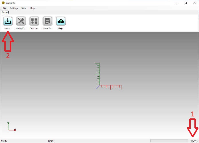
Before importing a file, click on the Status Information Options icon (#1 in the image above) in the bottom-right corner. This will bring up the visible information items.
By default, the Progress Bar, Status Label and Tool Tips are enabled and the Messages are disabled. We will turn on the Messages prior to loading the file so that we can see what the application is doing. Clicking the Messages option enables the Message field on the left of the screen and will also save this for future start-ups.

Now we will load the file into the application by clicking on the Import button, #2 in the image and selecting the block_tutorial1.stl file downloaded from the link above. This file can be stored wherever you want, if your browser did not ask for where to download the file to, it will likely be located in your 'Downloads' folder (which is a shortcut to your C:\Users\your_user_name\Downloads\ folder).
Once you have imported the file, you will see the layout as shown in the figure below:
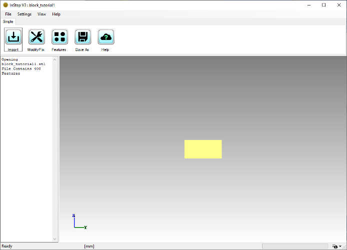
Simple Interface, Step 2
Imported STL File

Several items are worth mentioning here. The first is that the message field on the left shows the file that has been imported (also given in the title) and that it contains 408 Features. Here, the term Features refers to individual triangles. In general, we will adopt different terms, such as facet, feature or face to essentially all mean the same: a region bounded by edges. For STL files, these will always be triangles.
We can show the individual edges of the triangles by going to the Menu and under 'View' > 'Visibility' choose 'Show Edges' which turns on the Edge Display. Note that the keyboard shortcut for Edge Visibility is Alt + 'E' and similarly for Faces Alt + 'F' and Alt + 'V' for Vertices/Points. Toggling Visibility of the different items on and off is a great way of getting a better feel for what the data loaded consists of and often issues and similar can be (visually) determined simply by turning items on or off.
With the Edges turned on, it is time to rotate the body around and get a better idea of what has been imported. Using the Mouse and holding down the left button, the part can be rotated. By holding down the right button, the part can be moved (panned) around. By holding down the middle button (if available) or using the mouse wheel, the part can be zoomed in and out.
One important -and very helpful- tip is how the rotation center can be set. Frequently, a specific region is of interest for closer inspection and the best way to focus in on that region is to set the rotation center at or near to this region. This can be done by clicking on the region of interest using the middle mouse button (just a regular 'click', not press and hold). This will set the rotation center - which can be made visible through the same menu or by using the shortcut Alt + 'R'. When enabled, this will show a small pink point at the center of rotation. This will also set the maximum zoom distance for zooming with the middle mouse button drag option (pressing and holding the middle/wheel button and moving the mouse up/down will zoom up to a maximum proximity of this point, but no further).

With the Edges displayed, the data can be reviewed and any possible issues noted. For this tutorial, the data loaded does not contain any issues and is of relatively simple design. Nevertheless, it is worth pointing out how the STL file format triangulates all data, the holes are not defined by circles but rather a number of flat triangles. Depending on the source of the STL file, the number of triangles that are used to approximate a cylinder varies (or rather than number of divisions/angle for a full circle vary).
The next step in this Tutorial is to convert this body into a more suitable format. For this basic file, the process is straight forward and done by clicking on the 'Features' button. Small files convert quickly and for this file the result of this is shown in the figure below:
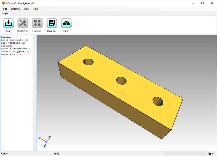
Simple Interface, Step 3
Converted File

Here, the edges are still visible, but all of the interior triangles have been merged to other shapes. The Message field on the left of the screen informs us that there were 3 cylindricals, 2 polygons and 4 quadrilaterals found. This corresponds to what the image shows. The top and bottom (where the holes are located) are considered 'polygons', shapes that are flat but can have any form of perimeter and interior combination. It is important to note the necessity for Polygons to be perfectly 'flat' and not just 'appear flat'. Any set of surfaces that have a small deviation will not be considered for suitability in a Polygon group.
Though this process is fast and has led to a clean result, this is not always guaranteed. Only in relatively simple cases such as this can the entirety of the body be converted to a representation that is completely defined by well-formed features. More often than not, the result will be a combination of features and remaining triangles. These cases can and often do pose issues to other applications and may require further considerations. This application does have other ways of dealing with more challenging cases as discussed in later tutorials.

The last step in this tutorial is to export the data using the 'Save As' button. Note that once the application has completed a step (the Features conversion in this case), the previous steps will become disabled as, for example, the Modify/Fix option cannot be applied to the Feature based data.

Clicking the Save As button brings up the familiar file save dialog box. Note that other file formats are available beyond the STEP format. In some scenarios it may be desirable to export to a different format though it should be pointed out that, for example, exporting a body that has been converted to a Features based definition into a format, such as STL or OBJ, that only supports triangles will essentially undo the previous conversions. The main purpose of the Features conversion is that the resultant file be of type STEP which can represent the shapes being defined (and is somewhat given, this is the InSTEP application after all).
Export of small files is generally very fast, to the point where you may miss the progress bar updating. Note the label in the bottom left border of the application will show 'Ready' any time the application is not actively performing an operation.
Looking at the resultant file, the export.stp is 11.1kB in size compared to the input file which was 20.0kB. If the Features conversion had not been done, the resultant file would have simply converted each triangle to a similar representation in STEP, resulting in a file 187kB in size. In some cases, it may be necessary to forego the Feature based conversion if it cannot correctly identify the underlying shapes.

Next: More Settings & the Guided Interface >>