The process has been made surprisingly straight forward even for converting large bodies to NURBS Surface models. The term
NURBS stands for Non-Uniform Rational Basis Spline and is
one way that smooth surfaces are represented in CAD applications. They should be considered for cases where there is no geometric equivalent
such as a circle, arc or straight line. For organic shapes, NURBS surfaces are really one of the only ways to represent the data (other than
using a lot of small triangles to approximate it - which is supported by InStep as a default form if no other conversions are applied).
We will explore the items that go into this conversion using the example file of the Lady. Please note that there is a dedicated NURBS-Surfacing Help Page for the Surfacing tools.
Importing the example, clicking on the RevEng tab and picking the Surfacing tool is shown below:
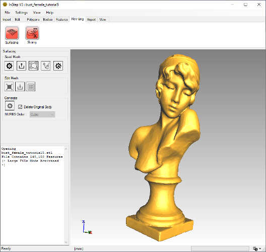 Imported Organic Body
Note that when clicking on the Rev-Eng tab and then on the 'Surfacing' tool will usually cause a very brief delay, during which important data about the body/bodies is calculated.
If multiple bodies are detected, a dialog box will first ask to split the data (unless the data is fractured/not properly sewn together, it is highly recommended to split it first),
and then an additional option appears where the body to be worked on can be selected (otherwise all bodies are used). It is recommended that one body at a time
be used, so it may be necessary to manually split data (see Tutorial 3) and perhaps first export them to individual files before importing and working on them separately.
The available Surfacing tools are split into three categories: Seed Mesh, Edit Mesh and Generate. The process works top to bottom with the Edit tools being
optional.
The following items are available under the Seed Mesh Group:
 Auto Generate Seed Mesh
- This is the recommended option which automatically generates a seed mesh based on simple criteria
 Import Seed Mesh
- If a seed mesh has previously been generated/exported for this body, it can be used as the starting point
 Manually Define Seed mesh
- This allows the mesh to be manually generated by picking from the viewer. This option is useful for cases where only a small region is of interest.
 Clear
Clear- This clears any previous seed mesh
 Settings
- Additional settings specific to the Surfacing tool are accessed from this (applies to different Surfacing options, not just seed mesh)
Importing a mesh is provided as a way to either first generate an automatic mesh and to then externally (i.e. in Blender, etc.) modify it prior to re-importing it
and using as a seed mesh. During import, the mesh is re-projected onto the body's surface and any triangles are merged to a shape similar to a quadrilateral.
Note that it is important that any mesh being imported be a continuous mesh (no separate sections).
The manual mesh generation is detailed in the Manual Surfacing Help Page for the Surfacing and is useful when smaller sections are of interest and the additional time to create
this helps in defining the region of interest.
For this Tutorial, we will use the Automatic option, for other options, please refer to the Surfacing Help Page.
Click the Auto Generate button which brings up additional options:
- Patch Count
- The slider and input field allow definition of how much detail is of interest. By default, it will set the value to slightly above 5% of the original
number of triangles. The value cannot be less than 100 and not more than 100,000. If the application determines that the value is outside of
its recommended range, the input field will turn a light yellow, if it cannot use the value, it will turn orange.
- Re-Sample
- The Re-Sample option is there to bridge small gaps or to generate a new mesh from the original for cases
where the original may be very coarse in some regions and very detailed in others. If the data comes from a 3D scan, the mesh is generally
quite uniform and this option can be turned off. If the source body is not a closed, solid body, then this option will be turned off by default as the application
expect a solid body and will otherwise need to take the perimeter into account. It is strongly recommended that, if the option is originally turned off, it remains turned off.
If the Patch Count is set to a small value relative to the original number of facets, it is possible to accelerate the process by modifying the Sampling cell count and cell size
from the Surfacing > Settings > Re-Sampling: ResampleCellCount & ResampleCellSize. Setting these (both) to a value of perhaps 64, allows the process to run faster as it halves
the number of samples along each axis (compared to the default value of 128). This effectively means that the process should complete up to 8x faster (though there are other items
that are to be considered). If proves to be difficult to obtain a good Seed Mesh using the default values, changing these can help though the rule of thumb is that the values should be above 30 and
the CellSize should be equal or larger than the CellCount.
- Curve Sample Points
- This is the number of points that the seed mesh is to assume are between the end points of the mesh it will generate. This value should be kept in
the range of 0-10. This value also determines the highest Order that the NURBS surface can be defined by (0 curve points means a straight line). Keeping
this value at 4 is generally recommended but if the resultant surface is to contain regions of stronger 'bends', then increasing this to perhaps a value of 6 is appropriate.
A larger value here will directly translate to a larger file size.
For now, we will not make any changes to the options, so we will keep the Patch count at 8128, re-sampling enabled and curve points set to 4.
Click 'Generate'...
After a few seconds, the progress bar will start to show progress and once it is finished, the display is updated to show the preview of where the
seed mesh identifies the NURBS patches to be located later:
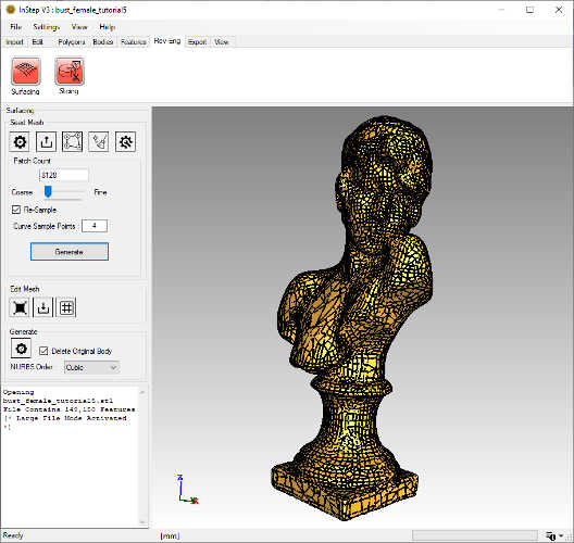 Automatically generated NURBS Seed Mesh with default options
This mesh looks fine but is perhaps more detailed than necessary. We will repeat the seed mesh generation: select the Patch Count input box and
type '2000'. Click 'Generate'. After a few seconds, the mesh preview is updated:
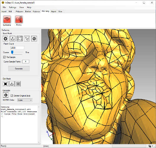
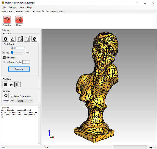 Automatically generated NURBS Seed Mesh for 2000 patch count
This mesh looks appropriate for the level of detail that was initially provided. Further refinements could be considered such as reducing the count,
adding more/less curve points and similar.
The next, optional, step is to 'smooth' (or perhaps more accurately, 'relax') the mesh. Under the Edit options, the first tool provides a smoothing iteration
(number of internal iterations and factor are defined in the Settings). Click it...
Likely, you will not see the changes, but there are some very subtle changes applied to the mesh where some corners are allowed to move in such a way
that the quality of the individual patch is improved. For this example, we could have left this step out, but it is worth considering in some cases where the
mesh may be more distorted due to size or source body.
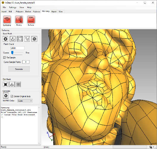
One more change we want to apply is a local refinement around the mouth. Currently the lips are defined by only a handful of patches:
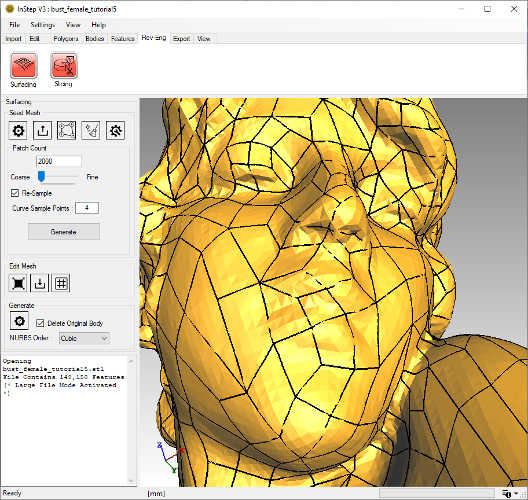 Patch preview in the face area
To locally refine the mesh, we use the 'Subdivide' option: 
Click it (which toggles the tool to be turned 'on') and move the mouse into the viewer. Hovering over the individual patches provides a preview
of which item will be sub-divided. Click the items of interest and then click the tool button again to turn it 'off'. The result should be something
similar to the image below (each item selected gets split into five sections):
 Locally refined mesh
At this time, all definitions have been provided and the original mesh can be converted to a NURBS body. Ideally, you will want to replace the original
body (keeping the 'Delete Original Body' checked) as this makes the process easier and prevents otherwise overlapping data from being accidentally exported. It is further recommended that the
NURBS Order be set to Cubic. Setting this to Quadratic is fine too but does not provide the same level of smoothness. Similarly, setting this to Quintic
can be problematic for some CAD applications and generally results in quite a bit more data being generated. The available options depend on the number of Sample Points previously chosen.
Once all choices have been made, click the 'Generate' button: 
The process of converting the original mesh data to the NURBS surfaces is generally quite fast but can take some time for large source bodies or large
number of patches. For this example, the process should only take a few seconds during which the progress bar will show the status.
Once completed and with the Edge display turned on (Alt+E), the resultant surfaces can be seen:
 Resultant NURBS Surface body
Exporting this follows the usual process though there is a shortcut at the top of the Rev-Eng tool bar: 'Surface' (disk image, which becomes available once the Generate has been completed). This allows all bodies that
have been converted to NURBS surfaces to be exported while skipping any that are not of this type. For this example, there is no difference, but if other bodies
were still present (or the original not deleted), then this would be helpful to avoid picking individual bodies for export.