Once the example file has been imported, we will switch to the Rev-Eng (Reverse Engineering) Tab. Note that if you have followed the previous tutorials,
it may happen that the import completes but you do not see the body. This is most likely due to the Setting we changed to prevent a reset during import. if
that is the case, go to Menu: Settings > Application Settings and change the ResetViewOnImport to 'True' from the Behavior Category. You can also manually force
a complete re-draw of the data using the shortcut Ctrl+Home (or just the Home key to recenter the view).
You will now see the imported Body:
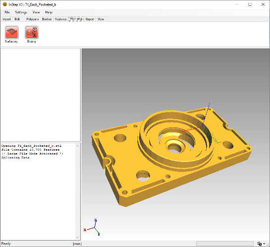 Imported Mechanical Body
We could certainly use the Features options to attempt to detect all the different surfaces and then directly export this for use in a CAD application.
However, let's assume that we were given this part and were tasked with coming up with some fitting that can be attached to the cylindrical extrusion on top.
Using the entire part is quite possible, but considering that all we are looking for is the cross section of the round part, using the full feature conversion,
export and import is likely time consuming (hint: if you proceed with the Feature conversion, not all of the smooth surfaces are converted and therefore the output will still be very large).
Instead, what we will do is to create a sketch of the cross section and then export that as both a DXF and STEP file. To do so:
- Once the file has been imported, switch to the RevEng tab page
- From the two tool options: Click on the Slicing Tool
- Find the Option to 'Add a new Slice':

This brings up the Create Slice tool box:
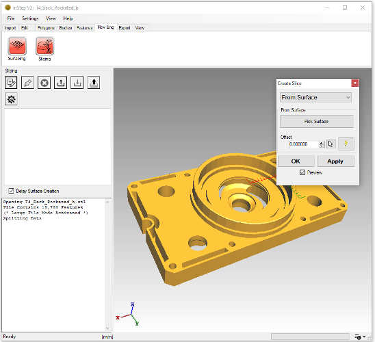 Adding a Slice in Rev-Eng:Slicing
There are several different ways to create a slice through the body. The simplest is to use the 'From Surface' which uses an existing surface / triangle as the definition
of the slice but allows the cut-plane to be offset parallel to this: Select the 'From Surface' drop down if not already selected. Now click on the 'Pick Surface'
button below and pick one of the narrower ends from the viewer. You can rotate the object just as you would normally and you will see the target
triangle highlighted for reference.
With the Surface selected, you can use the 'Offset' value up/down option to move the slice preview around (give that a try...) or you can pick a
point directly using the view pick option:

By picking a point from the viewer, we shift the plane to this location and the offset value gets updated. Though this is perfectly acceptable if, for
example, you want to move the plane to a well-defined point, for something like this, we want to pick the center point of the circular shape. For
this we will use the Advanced Point selector:

This brings up the point selection dialog box:
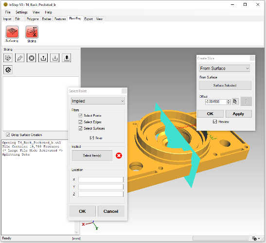 Advanced Point Selection options
Again, we have a number of different ways that we can select a point. The 'Implied' option is a way for you to tell the application by selecting a few items
and, if the application can make sense of what it is that you are asking, it will define the point... generally though, you want to be clear about what it is,
so for this case, we will use the option for 'Arc Center'. This selection tool works best when only edges are picked, so we will disable the 'Select Points' Filters
but otherwise keep the options at their defaults. Now click on the 'Select Item(s)' button and find an edge that is on the cylindrical section. If all goes well,
the application will recognize that this is part of a circle and will highlight the entire circle and insert a point at its center. Also, the coordinates will be
updated with this location. If it cannot recognize an arc/circle, try to select a neighboring edge that is also on the arc. Often, if it cannot determine the
circle from one edge, it can from two or three. If that does not work, check your edges (Alt+E) or try a different option. For well-formed surfaces, this option
generally works quite well.
If you are happy with the arc center point, click OK to apply this point to the previous ('Create Slice') dialog for the point through which the plane
is to be defined (still parallel to the one you selected). Once you are happy with the option, click OK to apply the slice and close the dialog box.
The best way to preview your slices is to toggle the Face display mode off (Alt+F). Now the only thing shown is the outline of where the slicing plane
intersects the body. In the left-hand view, you can see the Tree structure with 'Body 0' being the top most item (if there are multiple bodies, each
body will be intersected independently). Expand the Body0 item and you'll see the Slice 0 item. Clicking on this item will show the plane you created which
can be edited using the 'Edit selected Slice' option from above the tree view. Expanding the Slice 0 item shows the 'Surface 0' which now highlights in blue
when clicked on. If this slice were to intersect a body that contains an inside/outside, then the inside section would be in red, this helps to identify
what the application thinks is going on.
Also note that there is a check option below the tree labeled 'Delay Surface Creation'. This determines whether a (tessellated) surface is to be generated from the
Surface 0 item when it is clicked or not. Tessellating a surface can take a few seconds to complete and is generally not needed (if/when it is needed, it will be
automatically created). Give this a try nevertheless: un-check the delay option then click on the 'Slice 0' item and then again on the 'Surface 0'.
There will be a brief delay and you will see a grey surface appear. Also, you will notice that there is now a 'Surface 1' item under the Slice. This is because
the algorithm has detected that the two sections are not joined and has split them. You can click on either to show them.
For now, click on 'Surface 0' and then click the 'Delete the Selected Slice' tool button above the Tree. This will remove the selected item:
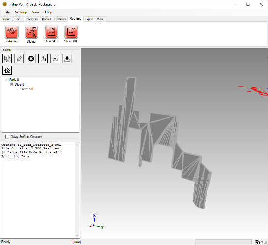 Remaining Slice after tessellation and deleting other slice
From here we have the choice to export this surface directly as a STEP file (in the Tool Menu there are two options: Slice STP and Slice DXF). Picking the
Slice STP exports the slices to a STEP file and they can be used just like other items - with the limitation that they are (flat) surface/shell bodies.
The other option, Slice DXF, generates a flat DXF file (rotated to lie in the XY plane by default) that can be used by CAD applications as a sketch for creating a
rotated shape from scratch. Often, having a cross section is all that is needed as CAD applications are often better suited to creating data in their native
format.