The basic environment consists of a Tree-View containing all generated slices, grouped per-body.
Each slice further defines multiple Surfaces which are represented either a lines or tessellated surfaces depending on whether the 'Delay Surface Creation' has been selected.
The image below shows a typical view prior to performing any slicing:
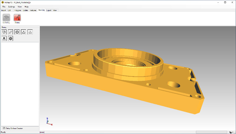 Initial Slicing Tool Environment
General Usage
The Slicing tool is primarily focused on generating reference surfaces or curves from otherwise complex data such as 3D Scan data or similar.
In a number of these scenarios, the purpose is to extract a definition of the imported data so that it can then be reproduced in
a CAD application. CAD applications are far more capable of working with Sketches (line drawings of the shape) than raw triangle data
and therefore it is often a laborious process to convert all the triangles obtained from a scan/model only to then use the CAD tools to
generate reference data that can be used for reverse engineering the overall (or partial) shape.
By using the Slicing tool, the lengthy process can be short-cut and reference data/sketches directly obtained from the triangle/facetted data.
Further, the Slicing tool allows two different workflows for this, one whereby sheet/surface bodies are generated at the intersections which
can be imported as surfaces located in 3D space and used as starting point to generate swept bodies or, alternatively, the intersection data
can be exported as DXF files which a number of CAD applications can import as a basis for Sketch data. Though the DXF files will (in generate, see the settings page)
lie in the XY plane as a rotation/projection, if the location of the data is less important than the shape, an efficient workflow can be reached.
Basic Steps
Details on the steps to obtain a Slice are discussed in the Slicing: Create page but it is worth discussing the general idea and options here.
- Define a Plane to act as a Slice-Surface
- Modify Settings to match the intent
- Export the Slices or convert to New Polygon data
- Import/Modify in CAD and apply any necessary corrections