 Guided Interface: Main Help
Time to read: ~7 min
The Guided interface (accessible through Settings → Interface → Guided (or through its shortcut: Ctrl+Shift+G) provides a more
'Wizard'-like approach to working through the conversion process. This may help in removing some uncertainty that is introduced with the
Expert level but provides some additional options that are not available in the Simple interface option.
With this approach, only two buttons are provided, the Help button (linking to this page) and the Start Button:
 Guided Interface: Start
The Start button - as the name implies- starts the Guided process by way of showing a tool-dialog box that contains the different steps.
Beyond this, the Viewer portion of the application (with all options on it) is still available and can be used to change things such as the way
that the graphical data is being represented or similar. Mixing the Guided interface with other tools that interact with the data
should be avoided wherever reasonable.
All of the steps of the Guided process are described in more detail below:
Import Page
Upon opening the guided interface, the first page shows the Import option:
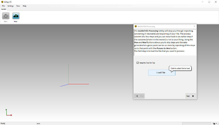 Initial view of Guided Interface
Here two options are available: selecting the file through the Load File button or to toggle between keeping the guided dialog box on top
(which will always show the tool box over other windows).
Opening Files
The Open File dialog box has a number of options for filtering the file format. By default, STL and OBJ files (Common Formats) are set but
other options can be selected too.
Once the data has been loaded, the next step is reached by clicking the Next button at the bottom of the dialog box.
Units/Scale Page
As mentioned in the page-description, Polygon files generally do not define units. Boundary Representation files (such as the STEP files)
require definition of units. For this purpose, units can be selected and - if necessary - a scale-conversion can be applied.
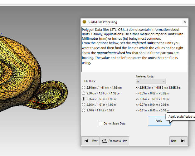 Option to scale the data to match units
The options may seem slightly overwhelming at first, so a few clarifications are in order:
- The (radio-) buttons on the left-hand side provide the options for what units may be assumed that the original file was saved/created in.
- The items on the right show what size 'box' the contents of the file would fit in. This is a simple x/y/z size that is obtained by taking
the values on the left and applying the unit scale conversion based on the units picked from the dropdown box. In other words, the user should
pick a unit from the options under Preferred Units and then select the row which shows a box size on the right that 'feels' right.
- The option to Do not Scale Data enforces that the input and output units be the same (whatever selection is made for the output units
is forced onto the input units and vice versa).
The choices for units are applied upon clicking Apply. Skipping past this (by clicking 'Next' without first applying the unit
scale) is the same as keeping the current scale and working units (shown at the bottom of the main screen).
The button labeled Process to Here is a kind of 'Undo' button. It is available on each page other than Import/Export and re-applies
previously made choices other than what is shown on the current page. If unit scaling is applied but the result does not seem correct, it can
be undone with this button and then re-applied. For very large files this can obviously take some time as it will completely re-load data from file.
Resetting items modified by previous steps is done by using the 'Prev' button and then processing to that step.
Repair Page
With several files, repair of the data prior to export may not be required. If it is however, whether this is due to underlying issues with
how the faces are defined or similar items, this page offers some options in what data is to be considered. The first three options
(Invalid, Duplicate and Normal corrections) provide basic corrections without greatly affecting the original surface data.
The fourth option, Repair Holes, closes any open sections and may or may not be appropriate, depending on the type of data.
The remaining options define whether advanced repair options are to be applied and whether these are to incrementally apply more and more aggressive options
to result in a final, closed set of data. The Before and After results should always be reviewed and if necessary, options left out.
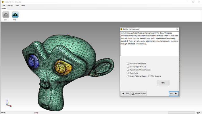 Option to perform some repair functions
As shown, part of this process is also to split data into separate bodies (if applicable). This is generally preferable and thus a default setting that cannot be
disabled.
Shell to Solid conversions Page (optional)
If the previous step is completed and it is determined that there are bodies that are non-manifold (aka. not 'solid' or shells) then this page shows.
If no shells are found, this step is automatically skipped.
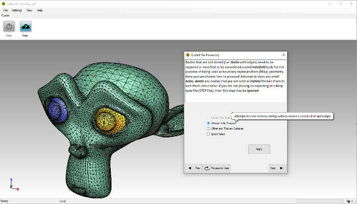 Option to resolve issues with Shell bodies
The issue with Shell bodies is that they do not form a closed, bounded set of faces, something that the STEP format expects (it can handle shell bodies
but will generally attempt to close them based on the information provided).
If the result is simply to export to a different polygon format, then this step can be skipped as they do not have the same requirements.
If however, the target file format is STEP/STP, then it is important to at least consider converting the data to solids. This can be done
in three ways:
- Delete Non-Solid Bodies (available only if there are some solids) removes all bodies that are marked as non-solid. This may be useful
for cases where a large number of individual bodies are detected but only a main item is of interest.
- Attempt Hole Closures provides a method by which smaller hole items are patched to (ideally) create a continuous, closed surface. This option
applies these corrections to all bodies that are identified as being shell bodies. This is the same process as for the Repair page, but can be used here as an
alternative way to resolve remaining issues.
- Offset and Thicken Surfaces is applicable if the underlying data represents a partial section of data (i.e. partial 3D scan of person's face).
The offset surface is generated on the backside (and reversed) to represent a thin solid.
As with previous items, the selection is only performed upon clicking 'Apply' and previous steps can be re-generated up to this point with
'Process to here'.
Feature Detection Page
Feature detection, the process of converting groups of facetted surfaces to their idealized geometric representation, can be useful in
cases where the underlying topology closely represents such features.
The options are to
Keep as Triangle-Only Data which does not apply feature detection,
Detect Flat Surfaces only which searches for items that are flat (and interconnected) or
Detect All Features which performs all available conversions where applicable.
It generally makes sense to use the All Detection option for cases where a reasonably high level of geometric items are expected and to Keep the
data as-is for cases where no such data is expected.
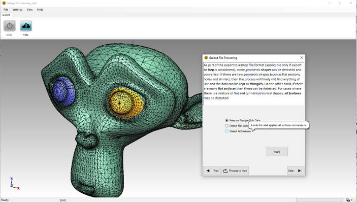 Option to detect features
If the data is more 'organic', such as a face or 3D scan, then it is less likely that a large number of features will be detected. For the case
of 3D scan data, it is often assumed that because the original data may come from something that does have strong geometric features, such a conversion
should be straight forward. Unfortunately, the scan process introduces a large amount of noise into the numbers which often cannot be removed
without first processing the data through a noise reduction process.
Export Page
The Export page is where the final step, generating the output, is initiated from:
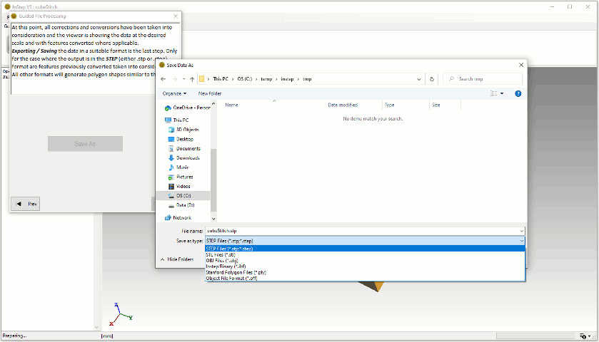 Export Options
Just as with the import, output of the data allows selection of specific filters. In this case, the output format has some additional
restrictions however. If the file format is one of either STL or OBJ, then the internal processes are used to generate this file and
only triangle data is written to the file (no features). The STEP format (either .STP or .STEP) generates the full set of data including
features if such were detected/generated.