Writing Data to Files: the Export - Tab
Time to read: ~4 min
The export tab is where data is written to the output file for use in CAD applications. Note that there are some specialized export options (For Reverse Engineering tools),
the Buttons on the Export tab apply to all currently loaded data.
 Export Options
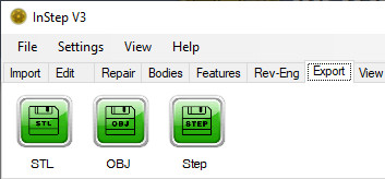
Each file format is briefly described below:
 STL
STL
The export to a STL file (STero-Lithography) is started by clicking the STL button. This brings up a save dialog box which allows
selection of the usual items such as location and file name.
In addition, the drop-down filter allows selection of either Binary (Default) or Ascii formatted STL files. The binary files will always result
in a more compact file that contains exactly the same information as an Ascii formatted file. The higher density is due to the way that the
data is stored, using multi-byte values to represent locations/coordinates rather than explicitly writing out the values as a text.
For the most part, use of binary files should be considered for all cases other than where the receiving application does not support them.
An important thing to note is that STL files only support Triangles and do not carry units. Therefore, if the data has been modified to obtain features,
that information will be lost and the underlying triangle data will be (if possible) restored during the export. Lack of units
(i.e. 'mm', 'cm', inch' or similar) may also result in scaling of the data and may need to be accounted for.
 OBJ
OBJ
The OBJ file (Alias Wavefront Object File format) is a more complicated file format in that it accounts for connectivity between items.
Whereas the STL file format simply represents triangles with multiple instances of the same points, OBJ files define locations once
and then reference those points in the definitions of the faces.
The implementation of the OBJ format is kept as simple as possible, intended to make cross compatibility as high as possible. Some applications
can make use of higher end definitions (such as high point count polygons), but in this case any feature detection is not transferred into the
OBJ files even though such features would be supported by a few applications.
In terms of file size, OBJ files will, depending on the underlying topology, generally fall somewhere between binary STL and ascii STL though it is
possible to have files that are smaller than binary STL files. If the target application supports both STL and OBJ to the same degree, then OBJ may
be the preferred option as it contains a clearer definition of its connections.
 STEP/STP
The Step (or STP per its extension) file format is the main purpose of the InStep Studio application. It is formally known as ISO 10303
with AP 214 being the specific Application Protocol being used in the formatting (defining Core data for automotive mechanical design processes).
If the application is simply used as a basic converter: STL file is imported then directly exported to STP, then the result is that each
original triangle present in the input data is converted to a bounded, trimmed plane surface and vertex and cartesian point information uniquely
defined. If it is possible to re-use normal and direction vectors, then they are listed by the smallest possible number of entries (as opposed to
simply generating an entry for each occurrence as most applications do it). Though this still results in a smaller file than a number of other applications
writing to this standard, the output will always be order of magnitude larger than the input file, in some cases causing issues with the
CAD application once there are more than about 20-50,000 faces being defined.
For small files, the direct conversion is no problem and should be considered. For large, geometric files however, conversion to
Features or through the Surfacing tool to NURBS surfaces
is encouraged as it can drastically reduce the file size and other issues when working with the files.
 Polys
Polys
The Polys-Export option is a 'catch-all' option for other polygon based file formats that may be less commonly used. At present the application only
exports to the Stanford/Polygon File Format (.PLY).
As users request additional formats to be supported, they will likely be grouped into this export option unless their structure is noticably different.
It should be pointed out that it is possible to manually select which bodies (if there are multiple) are included in the export. By default, all visible items
will be included but individual bodies can be selected using the mouse and then using a right-mouse click to open the menu, the body can be excluded from export.
 CAE
CAE
If the data loaded contains FE/CAE type mesh data (either by importing a CAE type Mesh file or using the 'To-FE'
option on the Import tab once a non-FE/CAE mesh has been imported, then the option exists to export the data to one of the supported formats.
The main difference between FE and non-FE mesh data lies in the use of the data (for numerical analysis) and what basic data is contained. Frequently, solid elements such
as tetrahedral, pyramids, prisms and hexahedral elements are used to approximate a shape. However, for cases where structural analysis is done with the data, shell elements
(essentially shapes that don't directly define a thickness) may sometimes be more appropriate and are supported through the use of triangular and quadrilateral elements.
For all elements, either regular (straight sided) elements or Hyperelastic elements (with an additional node on their sides) can be used if the file format supports them. For
scenarios where the mesh is used to run a Computational Fluid Dynamics (CFD) simulation, the mid-side nodes are usually not allowed.
The formats currently supported are: Nastran (.bdf, .nas and .dat), Ensight-Gold (.geo), Patran Neutral (.neu, .out) and ICEM Polyflow (.poly). Most CAE applications will usually
support one or the other for import/export operations.
It is important to note that data other than the geometric properties (elements and nodes) are ignored during import and are therefore lost during export.
For inquiry or support of additional formats or variations/corrections to existing ones, please Contact Us .