Obtaining a Manual Seed Mesh for a Selected Region
Time to read: ~4 min
The option exists to manually define a Seed Mesh for the NURBS Generation. A possible scenario where this would be of interest is in the case of using
a large amount of 3D Scanned data is available but only a small region is of interest, perhaps for creating a fixture or similar that interfaces with it.
For this purpose, the Manual Seed Mesh generation should prove useful and is initiated by clicking the Manual Seed Mesh option:
 : Manually Define Seed Mesh
This brings up the point picking dialog box:
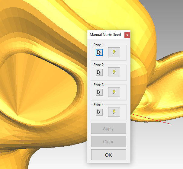 Manually Pick Seed Mesh Corners
This process is highly manual, but the tool should provide some help in obtaining a suitable mesh.
The tool requires that four points be defined on the source body. Unless the Settings have been changed, the application will automatically attempt
to order the selected points in such a way that they define a suitable seed Patch (order forms a Quadrilateral without intersecting edges and is oriented to face in the
same direction as the local source faces).
Once the first Point button has been clicked, the mouse will display a preview of the location in the viewer upon moving over the body. If there
is no other location near the mouse cursor, it will display a blue box where it will be inserted. If it is in proximity to another, previously inserted location,
the mouse will snap to this location and show a pink box to indicate that the points will coincide. Clicking the left mouse button then inserts the point.
In order to help the process, the selection then automatically moves on to the next point option or, if four points have been selected, to the 'Apply' button.
Pressing Enter will then insert the Patch and the process repeated for the next surface. Once all surfaces of interest have been picked, clicking OK applies any remaining selections or
clears the temporary data and closes the dialog box.
From here, the same options exist as for the automatically generated seed mesh (Edit, Generate) and the workflow resumes.
General Usage
The Slicing tool is primarily focused on generating reference surfaces or curves from otherwise complex data such as 3D Scan data or similar.
In a number of these scenarios, the purpose is to extract a definition of the imported data so that it can then be reproduced in
a CAD application. CAD applications are far more capable of working with Sketches (line drawings of the shape) than raw triangle data
and therefore it is often a laborious process to convert all the triangles obtained from a scan/model only to then use the CAD tools to
generate reference data that can be used for reverse engineering the overall (or partial) shape.
By using the Slicing tool, the lengthy process can be short-cut and reference data/sketches directly obtained from the triangle/facetted data.
Further, the Slicing tool allows two different workflows for this, one whereby sheet/surface bodies are generated at the intersections which
can be imported as surfaces located in 3D space and used as starting point to generate swept bodies or, alternatively, the intersection data
can be exported as DXF files which a number of CAD applications can import as a basis for Sketch data. Though the DXF files will (in general, see the settings page)
lie in the XY plane as a rotation/projection, if the location of the data is less important than the shape, an efficient workflow can be reached.
Notes
In general, this option is quite simple in its implementation. There are few options to revert or make changes once a surface has been defined. Points can be re-defined prior
to applying the data, so care should be taken to ensure that the surfaces are continuous where so desired.
The number of points inserted along the Patches' edges is defined in the Settings and follows the same logic as for the Automatically generated Seed mesh.
Creating points that coincide with existing features is supported by using the Dialog option next to the point selector. This allows more advanced locations to be defined such as intersections or similar.
If a large number of Seed Patches are to be generated, it is advisable to consider perhaps using the Automatic option and then exporting, modifying and importing the mesh. This allows a
generic mesh to be defined that fills any regions that are of less interest and lets the user focus on regions where a specific mesh is sought. Manually editing the mesh in this way is
discussed on the Export page.