Feature Detection & Conversion using the Simple Interface
Time to read: ~5 min
The Feature conversion capability is an option within InStep that allows features that are defined by a specific geometric shape to be
re-created using its core definitions (center points, radius and start/end points for a cylinder). This option allows facet-based data (specifically
those of STL and OBJ origins) to be compacted in a way that is more appropriate to their use in Boundary Representation (B-Rep) file formats.
The conversion is completely automatic and relies on a handful of parameters that modify some of the tolerance values. For the Simple Interface (as
opposed to the Expert Interface), these options are set to use default values that are appropriate for most of the anticipated cases.
Facet Based data
Though not all applications generate the same type and format of data, under the assumption that the faces/facets imported through the application
follow a reasonably accurate representation of one of the principal geometries (see below), the application can detect them and determine their parameters
based on the data provided. Usually, facet data looks (using the Edge Display, shortcut Alt+E) something like (shown in the Expert Interface):
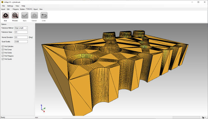 Facet Based Data
Here a number of geometries are interconnected in the body. The application uses a smart-search for the shapes while allowing some amount of inaccuracy
in the data. By applying logic rules to what data belongs to what group, the Features can be generated.
Feature Based data
From the original data, the following, feature based geometry is obtained:
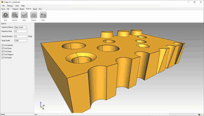 Feature Based Data
The Features shown have been correctly identified and re-created from their definitions. For each of the items obtained in this way, the
application will generate a corresponding surface during export to the STEP format (*.stp). Such surfaces represent an exact definition that
can usually be edited and manipulated by mechanical CAD applications.
Geometric Features
The following items are searched for and converted where possible:
- Cylinders (These can be either complete, 360-degree cylinders or partials). Both cutouts (holes) or extrusions (bosses) are implemented.
- Cones Similar to the Cylinders, Cones can be additive or subtractive and either form a complete or partial revolute. Additionally, Cones
can end in a single point tip or a circular surface
- Quad (-rilaterals) Essentially a combination of two Triangles that for a flat shape with four corner points. Only items with a reasonably accurate
(defined by Quality parameter) representation of a rectangle are considered as Quad items.
- Polygons are shapes that are flat (parallel and connected to each other) and define a larger (>4) number of perimeter points. They can be
continuous or contain cutouts for holes, bosses or similar.
- Triangles If none of the other surfaces are found to be applicable, the original, Triangular shape is maintained but, if necessary, corrections to its
boundary are added to make the shape continuous across neighboring surfaces (such as for example where a Triangle encounters a cylinder edge).
It is important to keep in mind that these shapes are idealized and, if the original data does not meet the minimum requirements, then the input data
is maintained by keeping it as Triangle. This is usually the case where highly organic shapes are encountered (such as a human head) but also for cases where
3D scan data is used that contains high amounts of noise (i.e. small, randomly introduced location errors due to precision or other factors). Those
shapes cannot currently be processed in this manner and it is frequently not worth attempting to generate Features from shapes that will ultimately not
benefit from this process (not to mention that it can be time consuming).
Detection Issues & Problems
As with most 'automated' processes, there is a chance that things don't end up the way they should. One of the most likely candidates for
this with the Feature conversion process is tolerance of the underlying data. If perimeters of a cylindrical feature are misaligned by a fairly large
percentage, even though they 'look' like they would lie on a circle, the application may not be able to correctly identify them as such.
Further, it is often though incorrectly, perceived that a large amount of data is the same as accurate data. If the viewer shows a smooth surface,
the understanding goes, then the application should be more easily be able to detect it. Unfortunately, this is not correct. In fact, the opposite (to some
degree) is true. If a hole is represented by (for example) 30 edges then each edge will form an angle of 12 degrees with its neighbor (12x30=360deg). In this
case, it is easier to determine the approximate center of a circle that the two lie on as it is possible to intersect two perpendicular vectors through their
centers and thereby reaching the center point. In the case where there is a very small angle, the error in their shared intersection point is far greater
when compared to that of other edges on the same assumed circle.
The takeaway of this is that data shouldn't be made to 'look' very smooth by introducing a large number of refinement steps as that only adds to the
confusion in going from facet based data to boundary representation (not to mention that more data also means slower processing).
Lastly, tolerances are relative to the size of the bodies in question. If the units applicable to the data are incorrect by orders of
magnitude, will the tolerance, likely resulting in either fractured items or other irregularities.