Generate the NURBS Data
Time to read: ~3 min
Conversion or Generation of the NURBS Surfaces from the original data using the Seed Mesh is accomplished by
clicking the Generate Button at the bottom of the Surfacing Tool Groups:
 Clicking the Generate Button converts the data to NURBS
The tool group is fairly self-explanatory, but a few details may be of interest
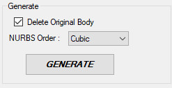
Generate
The Generate button starts the process using the original source data and the Seed Mesh to define the layout and locations of the patches to convert.
Beyond this, the conversion also needs to define the Order of the NURBS Surfaces to create. The Order is a direct correlation to the Degree (= Order-1) and
is a measure of how smoothly the surface can change. This is essentially a polynomial that, similar to generalized polynomial curves, defines how the shape can change.
The implementation being used here allows either Linear, Quadratic, Cubic or Quintic orders/degrees and is a function of the number of points being used to represent the sides of a patch.
If fewer points are being inserted, the available options in this drop-down box will change to represent the range of options available. In general, a Cubic NURBS Surface
should reasonably well represent the data.
One item to mention is that currently all surfaces are explicitly defined as being G0 continuous, meaning that -unless there is an issue with the data- surfaces are said to be continuous from one to the next
but that tangency (G1 continuity) or flow (G2) is not provided. Future versions of the application may address this, but for now these higher levels of continuity can be, to some extent,
provided by using surfaces that are sufficiently smooth to begin with. If the number of patches operating from this is reasonably coarse, a tangency, though not
explicitly defined in the data, becomes reasonably well approximated.
Delete Original Body
The option exists to replace the original data with that obtained from the conversion. In general, it is recommended to use this option as it brings with it an improvement in
speed and memory requirements. However, if only part of the original data is being converted, then this is likely not desirable. Clicking this option deletes the original body once the necessary information
has been obtained.
Considerations
A number of options are available as to how the process is completed and it is recommended that the user attempts a few different options to judge what combination of parameters provides the best option.
As a starting point, default values are recommended as those are values that have been used or obtained during development. Changing some of the values beyond what they were expected to provide
may result in application failure due to memory overload or similar or may just make the application process the data in a very slow fashion that is indistinguishable from a 'hanged' (unresponsive, frozen) application.
The main use of the Surfacing tool is to allow organic shapes to be converted to ones useful in a CAD environment where it may be difficult or impossible to recreate using
any other method. As this tool is intended for use by hobbyists, students and engineers and professionals alike, an attempt has been made to keep things simple and straight forward
without going into detail about how knots, lofting curves and similar are defined or manipulated. With this obviusly come some limitations.