InStep Studio

INSTEP STUDIO 3D

Tutorial 3 - Workflow with Expert Interface

It is our hope that the Expert Interface will eventually become the go-to interface for all users. There are a lot of options available and some of them can be confusing. In this Tutorial, we will discuss the overall workflow that applies to working with the full set of capabilities.

Other options for Reading/Learning

Alternatively, you may want to
Download as PDF
Watch the YouTube Video

Please click on the items below as we progress through this tutorial

Previous Tutorials discussed the Simple and Guided interfaces and provided a number of basic items to consider when working with files. It is recommended that you first read through those tutorials as they contain useful information that will not be repeated here.
When the application is first started, a dialog box appears that asks for the interface to load. The setting can be remembered by disabling the option to ask for this during every start up. If the application has been started with an interface other than the expert interface, it can be set as the new default by going to the Menu option: Settings > Interface > Expert.
The Expert Interface is shown:

Expert Interface
Expert Interface

Aside from more tools, the only item to point out that is different here from the other interfaces is that different tool groups are combined in their individual tab pages. The Application, starting at the top border, shows the Application name ("InStep V3" together with the file loaded once done) followed by the menu bar (File, Settings, View, Help) and the individual Tool-Tab Pages (Import, Edit, Repair, Bodies, Features, Rev-Eng, Export, View).
Aside from these, an additional tab page (Elements) gets inserted once a file is imported that is defined by a Computer Aided Engineering (CAE) format such as Nastran/Patran, Ensight or similar (this is discussed in a separate Tutorial).
First, click on the different tab pages to get an idea of what options are available. You will find that different pages offer additional options.

The workflow, as previously mentioned, is relatively simple and is generally expected to proceed in a left-to-right fashion through the different tab pages. Frequently, skipping one or more is common, especially the Edit page which represents a low-level editor to individually create triangles to repair specific issues. The last page, View, contains options for changing the way that the view shows the current geometry/data.

The center of the application, contains the 3D-View of any imported data and the right and left borders can hold additional tools, depending on the current tab page and options selected. At the bottom of the page are general status fields. By default, in the far-left corner the status label will show whether any tasks are being processed. A 'Ready' indication will let the user know that the application is (usually) awaiting input. To the right of this is a unit label (by default '[mm]'). This shows the working units being used. Clicking on this allows the user to change the scale and units though some consideration of this are in order as the units also affect tolerances behind different processes.
In the bottom right corner of the application are task progress bar and the status options. Clicking on the status options menu brings up options to turn on/off any of the previously mentioned items as well as to show the Message Panel. This last option is useful to provide feedback about tasks being worked on and results of those tasks (such as number of features imported, issues, etc.). It is recommended that this option be turned on.

A simple example file will be used to illustrate the processes and their effect.
You can download the example file here:
Example Blocks File (STL)

File Import
Importing File in Expert Interface

Importing this file triggers a warning: "This file appears to contain multiple parts." The application has detected that there is more than one body present in the file. The option is presented to Split the data into separate bodies. Further, an option is provided to make this the default behavior.
It is important to understand this warning message and the presented options. The data shown in the viewer clearly consists of several blocks that are not connected or even touching (the individual bodies are recognized based on whether they share edges, not merely whether they have overlapping surfaces). If the data is kept as a single body, all processes that may be applied later on will make the assumption that all of the data is continuous and may result in strange behavior. For this example, splitting is clearly the correct choice. In other situations, however, the choice may not be as simple and often, especially when the data comes from 3D-scanners or similar, there are small sections that are not quite attached but should nevertheless be considered part of the same body. Those cases are left up to the user to decide whether they are better treated as a single body or as multiple bodies.
Even if this is initially skipped (setting the option to make this the default and then choosing 'No' is the fastest way to import files), it can still be done later from the Bodies: Split tool.
Usually, however, it is desirable to let the application automatically split data, so choosing the 'Yes' option after first making that the default is recommended. In cases where bodies were split but should not have been (a less common case), the data can be 'Merged' back together, also an option on Bodies: Merge.

With the Splitting option selected, the view is automatically updated (and the Message Panel shows this too) with different colors applied to each body.

Any data loaded contains some amount of information, both of a geometric nature as well as things such as number of bodies, facets, etc.
Accessing this information is easily done from the Import Tab: Info

File Data Information
Information about the imported data

There is not a huge amount of information available, but it does provide the bounding box size of all and individual files, their centers, number of features and similar. Displaying this information does not represent a necessary step, but it can be helpful when troubleshooting issues or for cases where different files are compared, for example when a binary STL is imported that "feels" larger than a different (ascii) file that has a larger file size but "feels" smaller... the information panel will provide the number of bodies detected and number of facets for each.

The data loaded so far may contain several bodies that are not of further interest. This is often the case where a part has been 3D-scanned (perhaps the entire under-hood volume of a car or similar) but only a small region or a single body is of interest. If the surface is continuous (i.e. forms only one body) then other tools may be needed to separate the item(s) of interest (we recommend Blender). If there are separate bodies however, we can do so using the Bodies tab:

Delete Bodies
Deleting Bodies

Once on the Bodies tap, individual bodies can be selected in the viewer (or if necessary, a body can first be split into individuals using the 'Split' Tool button).
By Right-Mouse clicking anywhere in the viewer, the options are brought up for the currently selected bodies. The choices are quite self-explanatory with the Thicken, Simplify and Re-Mesh addressed in their own tutorial. For this simple example, we will keep the body with the conical hole in it (conical with a flat bottom). Two ways are possible, we can either manually select all the others and then pick the 'Delete Bodies' option or we can pick the one we want to keep and then choose the 'Delete All Others'. In either case, the other bodies get removed. Depending on the files you may be working with, it can be a prudent choice to perhaps export bodies individually in this way so that you can process them one at a time. This also reduces the memory overhead for some other operations.
If an approach is chosen whereby the original data is split and individually exported to (perhaps) STL files, a different approach can be chosen as the Export tab has a similar option to deleting individual bodies: it allows you to select a body and export only that body to a format of your choice.

For the purpose of this tutorial, we will assume that all bodies other than the one with the flat tipped cone have been deleted. Usually we can proceed from this, however, one item that can happen is that when a large number of bodies are present, the view-rotation center is so far away from the remaining body that viewing it becomes difficult. As mentioned in the first tutorial, we can manually set the rotation point to any existing object. However, when the data is reduced in this way, it can also become necessary to 'reset' or re-center the view altogether. You can do this using the 'Home' key which determines the center point of any loaded data and sets the view to be centered on this. As a side note, if ever there are graphical issues, perhaps due to unplugging a monitor or similar, a full re-draw can also be requested using the key combination Ctrl + Home. This not only re-centers the view but also refreshes the underlying data (and can therefore take a bit longer to complete).

With the single body remaining (it is generally recommended to only work with one body at a time, but most tools will accept multiple bodies and process them in turn), we will switch to the Features tab which is where more advanced features (polygons, cylinders, cones) are obtained from a triangle-only collection of surfaces.

Features Tab
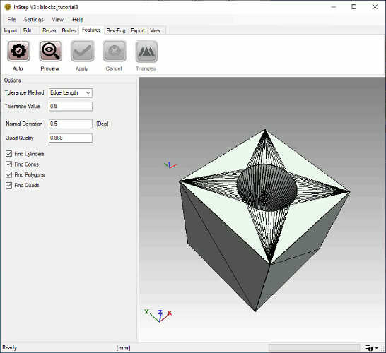
Body in the Features Tab

Here the edge display has been turned on (Alt-E) to get an idea of what the data consists of. Contrary to what might be expected, the underlying algorithms actually work better with coarse data (i.e. circles divided into perhaps a few as 10-20 segments). This has to do with how the application determines whether something forms a circle compared to a straight line.

The Features Tab does not have a large number of tools: Auto, Preview, [Apply], [Cancel]. The Preview Button searches through the loaded data and attempts to define groups of surfaces as one of the underlying shapes. If the preview looks good, the features are converted using Apply. If there seem to be issues, the preview data is cleared using the Cancel button. The Auto tool simply performs the preview and apply steps in one. It is recommended that the conversion is always first reviewed for issues.

In the options panel on the left, above the Message Panel, different tolerance options and search options are given. They are discussed below:

Tolerance Method
The individual shapes that are to be searched for generally are not 'exact' in how they are represented by triangles. This option sets what the tolerance value is to be based on: Shortest Edge, Diagonal of Body or an Absolute value. Changing this value can noticeably change the outcome... or not at all.
Tolerance Value
The value set here is applied to the setting above. For an Edge Length of 0.5, the tolerance value to be used is 0.5 x shortest edge. For Body Size, this is 0.5 x Bounding Box Diagonal. For Absolute, this is simply the value to be used.
Normal Deviation
This sets the deviation that is acceptable between neighboring normal vectors to be considered 'equal'. This value is only part of the consideration of what is determined to be equal or flat, so increasing it does not always result in 'more' data being found.
Quad Quality
The 'quality' value of any quadrilateral is a function of its corner locations and edge lengths. By setting a value of 1, the application will only consider two triangles as quadrilaterals if they form a perfect square. A smaller value will allow increasingly elongated rectangular shapes (or shapes with increasingly trapezoid-like shape). it is recommended that this value be kept around 0.5-0.9.
Find x
Individual Surface shapes can be included/excluded from the search. In some cases, the algorithms will detect shapes that they should not have. For those cases, disabling the problematic shape might result in a better or more useful outcome.

Irrespective of what the tolerance values are, shapes can only be determined if they follow some basic geometry. Items that the application cannot currently resolve are things such as off-axis holes (where one or more ends are not parallel to the other or where the circles are not flat). Blends, where a surface slowly transitions from one surface to another also represent problems. In general, only simple shapes are detected though this will likely be expanded in the future.

For now, an Edge Length method is chosen and a value of 0.5 used with all the other options at their default. Clicking Preview provides the view shown in the figure below:

Feature Preview
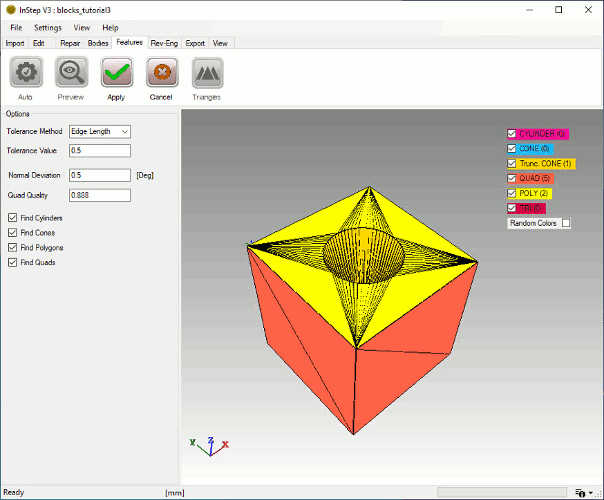
Preview of the detected Features

The process is quick and switches to a preview mode: on the right of the screen are the different types that the application internally supports. For this case, there are 0 Cylinders, 0 (Full) Cones, 1 Truncated Cone, 5 Quadrilaterals, 2 Polygons and 0 Triangles. The last item indicates that each triangle has been converted to a different shape. Note that each of these items can be turned on/off in the view to allow a better understanding of what a given surface has been identified as. For cases where a number of adjacent surfaces are present, they can also individually be colored using the Random Color option (give it a try..). Each time the Random Color option is chosen, a detected feature is given a different color - so if you don't like the choice, click it again to get a different color. It may also be helpful to turn Edges (or Vertices) on in the display using the Alt + E (or Alt + V) option to do so. Note that the original Facets are turned off in this Preview, if you manually turn them back on (Alt + F), the original and preview surfaces will coincide so turning individual detected shapes on/off will show the original/detected.

Once the preview looks fine, the detected features can replace the original surfaces using the 'Apply' tool button. This will also refresh the edge display to only show those edges that are represented by the surfaces. Cylindrical and Conical shapes that represent a full revolution (i.e. that have a closed circle not just an arc at their ends) are internally split into two as this representation works better for the STEP format.

One item to point out is that once the data has been converted to a Feature based (as opposed to facet or mesh based) representation, the other tab pages (other than Import, Export and View) will no longer be available. The only other option is on the Features tab: Triangles which essentially reverses the process and creates triangular facets from the surfaces.

The only thing left to do in this process is to export the data to a suitable format. A few items are left to discuss here in terms of available options on the Export Tab:

STL
This option allows export to either Binary or Ascii formatted STL files, selected from the dropdown box in the dialog box that appears. Binary STL are generally preferred as they are smaller and more robust but some applications cannot import them. It should be noted that exporting to this format will always convert any surface data back to triangles as this format does not support any other shapes.
OBJ
Similar to the export to STL, the OBJ option saves the data to the OBJ file format. This format does support some merged facets but should be limited to triangles and quadrilaterals.
Step
The Step export is the main purpose of this application. The file format is the AP 214 format which is generally well supported by CAD applications. One item worth mentioning is that if there are multiple bodies active, an additional export option becomes available from the drop down: Assembly Step File. This option is not well supported by CAD application but internally splits all data into individual Step files and creates an Assembly step file that references all the individual parts. It is generally recommended not to use this option - though it may be useful in some situations.

<< Settings & Guided Interface Editing and Repairing Data >>